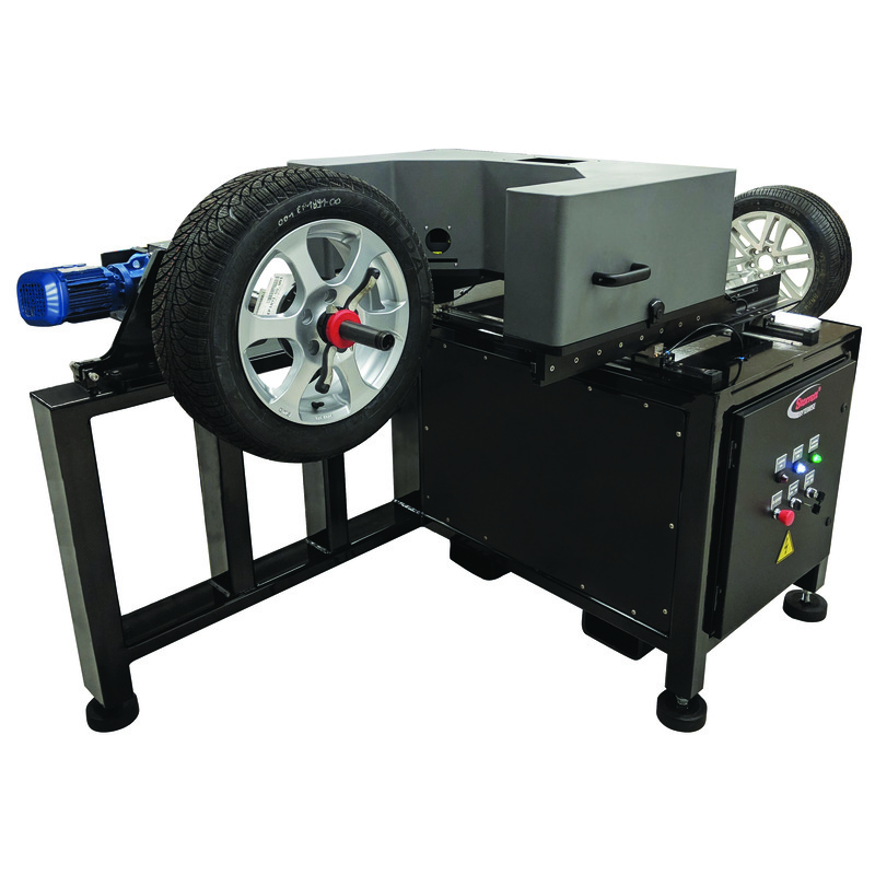
Tire360
WHAT DOES IT DO? Tire makers routinely measure production tires as a means of quality checking. Tire360 is a 3D tire scanning system that measures parameters like crown radius, section width, section height, circumference, and location and height of tread wear indicators. Tire360 can be used with our CTWIST tread wear analysis software. Tread wear testing is accomplished by scanning a tire sequentially during a wear test program. The CTWIST software module provides for the following analyses: tread depth profile, irregular wear, tread life prediction, tread loss profile and heel/toe wear.
WHY DOES IT MATTER? Tire360 can improve your workflow and reduce labor for routine tire measurement. Production tires can be scanned in less than 10 seconds and automatically analyzed for test parameters like crown radius, section width, section height, circumference, and location and height of tread wear indicators. Tire360 can greatly reduce the time needed for tire scanning in your tread-wear testing too. A test that takes 10 minutes with a fixed-point scanner can be done in 10 seconds! For a user checking tread wear for 10 vehicles per day the savings in testing labor is over 6 hours. That means 6 hours of additional driver productivity too - per day. Tire scans can be permanently archived so you can go back and analyze tires after they have been shipped out.
HOW DOES IT WORK? Tire360 is an off-line station that scans tires that have been pre-mounted on rims and inflated. The tire/rim assembly is manually mounted onto the spindle tooling. The machine rotates the spindle and scans the tire automatically. The system utilizes CrossCheckHD™ sensors in a multisensor c-frame array. CrossCheckHD is a family of high speed line laser sensors manufactured by Starrett-Bytewise in Columbus, Georgia, USA. These are referred to by many other names – laser stripe sensors, sheet-of-light laser sensors, and laser profile sensors. HD designates the high data-density version that utilizes a high speed CMOS detector, produced according to our specification. Each sensor projects a line of laser light across the tire surface, which is reflected back to the sensor through a lens and onto a CMOS detector where each profile is digitized. The digitized line is triangulated and converted to XY coordinates. A patented method is employed to transform, or stitch, the data sets into a common coordinate system Tire360 covers a large range of tire sizes by mounting the measurement head on a two-stage slide with one radial axis radial and one lateral axis. Axes are manually positioned and lockable. The axes are encoded in order to capture the true radius and circumference. Tire360 software combines the individual sensor data sets into a single bead-to-bead point-data file for each scan, and combines the data sets by associating the profiles to the encoder count. The data set is unfolded to visualize a 3D surface topography in a "false color map" with 16 colors spanning }2mm. This color map is normalized using a filtering tool-set to remove low-frequency runout. A full range scan consists of 16,000 columns and 7,500 rows of data. Each radial and lateral waveform can be displayed in the contour view window.


